

Automotive Vehicle Systems


Automotive Vehicle Systems
- Chassis
It is the functional support structure of vehicle systems responsible for passenger comfort (seating arrangements) and safety (cabin). This structural category can be divided into:
- Chassis: It serves as the structural and support function for mechanical components such as steering, transmission, engine, suspension, hydraulic and electrical lines, etc.
- Bodywork: It allows for the containment of the payload and ensures the accommodation of passengers and the driver.
In the current field of automotive engineering, there are basically two ways to construct the chassis, which are:
• Structural bodywork: There is a separation between the chassis and the body, each with its own function. Common in commercial vehicles and medium to large pickups, it is primarily composed of longitudinal and transverse elements known as ‘longerons’ and ‘cross members,’ respectively. They offer good bending rigidity and are well-understood and agile in manufacturing. Typically fastened by rivets, the elements can be replaced.
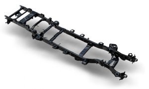
Source: FCA (2018)
The most commonly found material for this profile is steel, arranged in open beams, typically with a cross-sectional shape resembling a C or U.
• Unibody: This is the most common solution for small and medium-sized vehicles. It features a construction based on sheets, primarily made of steel, stamped into various shapes and joined together by spot welding and/or rivets. Some vehicles use structural adhesives. As a result, a closed structure is formed, which provides a high degree of torsional rigidity to the chassis as a whole..

Source: Crolla (2009)
To provide safety to the occupants, the unibody can feature various thicknesses of sheets and different materials, aiming for planned deformations in impact areas and superior resistance in the cabin, for example. Material and geometry optimization becomes increasingly necessary, aiming for weight reduction and emissions reduction.
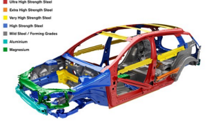
Source: Volvo (2017)
- Steering System
Used for steering and controlling the vehicle, creating the forces and moments necessary for changing the vehicle’s trajectory during its course. The change and control of trajectory can be actively performed by the driver or by the vehicle itself if it is equipped with autonomous or semi-autonomous systems. Basically, steering systems are based on bar mechanisms, whose geometry is designed to meet project requirements and steering capabilities.
The steering system can be divided into three basic components:
• Steering mechanism: It consists of the linkage system between the steering knuckle and the steering box through articulated arms and ball joints. The wheel’s rotation axis is around the kingpin, whose inclination relative to the vertical axis provides the caster angle.

Source: Genta (2009)
• Steering box: It is responsible for transforming the circular motion of the steering wheel into the movement of the tie rods. It can be a purely mechanical, electric, or hydraulic device, or a combination of them. Currently, most vehicles use a rack-and-pinion steering box with some form of power assistance for the driver’s effort. The trend is towards the use of electric motors for assistance.

Source: Çetin (2009)
• Steering column: It serves as a bearing support for the torque transmission shaft from the steering wheel to the steering box.

Source: Grimmer Motors Limited (2020)
- Brake System
A system used to stop the vehicle, reduce its speed, or keep it stationary. A properly sized braking system provides safety for both those inside the vehicle and those sharing the road, including pedestrians, cyclists, animals, and others. Vehicles commonly use disc brakes, drum brakes, or a combination of both. The actuation can be hydraulic, mechanical (via cables), pneumatic, electric, or a combination of these methods.
• Drum brake
Drum brakes are common in cargo transport vehicles, older vehicles, and on the rear axles of vehicles in general. They are cost-effective, easy to repair, and manufacture. They basically consist of a hydraulic cylinder that pushes a pair of friction material shoes against the inner wall of a drum, generating heat and braking torque.

Source: DPK (2020)
Commercial and transport vehicles such as trucks and buses predominantly use drum brakes, but their braking power is delivered through compressed air and acts on the shoes through an axle with an ‘S’-shaped end.

Source: SGI (2020)
• Disc brake
Disc brakes have become popular in the front brake systems of vehicles in general and are common on the rear axles of sports and premium vehicles. They basically consist of a rotor (brake disc), which can be ventilated or solid, attached to the wheel hub, and a hydraulic system (brake caliper) that has one or more pistons that press the brake pads against the disc, generating braking power and heat. The calipers can be sliding or fixed.

Source: AKEBONO (2020)
- Suspension System
The suspension system is responsible for filtering vibrations (providing comfort) of various amplitudes and frequencies, stemming from the road’s geometry, as well as ensuring maneuverability and vehicle dynamics performance for the respective suspended mass, allowing for the maximum possible contact of the tires with the road. The elements that make up the suspension system basically consist of: bar mechanisms (control arms, tie rods, sway bars, ball joints), elastic elements (coil springs, leaf springs, air springs, torsion bars, stabilizers, among others), and damping elements (pressurized or non-pressurized hydraulic shock absorber assemblies, bushings, mounts, and bump stops). Tires are also part of the suspension design and dimensioning, acting as springs due to the elastic behavior of the rubber combined with the compressibility of the internal (pressurized) air, whose behavior is nearly ideal. The material’s hysteresis (rubber) offers a certain degree of damping and vibration absorption for lower amplitudes. The figure below shows a seven-degree-of-freedom model for a vehicle with independent front wheel suspension and a solid rear axle.

Source: Nicolazzi (2012)
Suspensions can be divided into three main classes: Independent, semi-independent (torsion beam axles), and dependent (solid axle). Additionally, suspension designs can be categorized as either active or passive. Active suspensions are primarily available in more sophisticated (luxury) vehicles, providing minimal displacement of the suspended mass and high stability. Passive suspension is found in the majority of currently used automobiles, with its main components being the spring and the shock absorber. Below, we will present three examples: a dependent suspension (solid axle), an independent suspension, and a semi-independent suspension (torsion beam).
• Rigid Axle

Source: FCA (2008)
This type of suspension is mainly used in vehicles with a high carrying capacity, most of which use overlapped semi-elliptical leaf springs or a single leaf. In addition to serving as an elastic element, the spring limits the rotation of the axle due to the differential torque and also acts as a block to prevent longitudinal movement of the axle.
• Independent suspension

Source: Toyota Motor Corporation (2015)
In this configuration, both steering knuckles have exclusive degrees of freedom, meaning that the action of the right knuckle does not interfere with the behavior of the left knuckle. There is no connection between them, except for stabilizers and steering systems. A system that provides a lot of freedom of movement and allows for a highly refined dynamic response is the multi-link suspension.
• Semi-dependent suspension

Source: VETR (2020)
The suspension model described above has characteristics that are intermediate between dependent and independent suspensions. The two steering knuckles are connected by an element whose rigidity cannot be simply ignored. Therefore, the majority of them have an axle, typically of an open section, called a torsion beam axle.

7 dof model
- Powertrain System
The automotive system used to adapt the variable torque from the engine and transfer it to the vehicle’s wheels in order to achieve appropriate traction forces and speeds, according to the driver’s needs or the road conditions. Additionally, the transmission allows for decoupling and interruption of the torque flow to the wheels and, if properly sized, can provide conditions for maximum torque during vehicle movement, especially when starting from a standstill.

Source: Audi (2020)
Several mechanical systems with different transmission ratios are available to fulfill the aforementioned function. The choice of which solution to use is not simple and cannot meet the needs of all drivers, which has led to development and research in the major engineering fields. The transmission encompasses the entire set of elements, from the engine’s flywheel (crankshaft output) to the wheel hubs. However, only the variations of gearboxes or gearboxes, as they are popularly known, will be illustrated.
• Manual gearbox
Source: GM (2006)
Manual gearboxes, as the name suggests, are mechanical devices composed of paired gears with different transmission ratios. The input shaft is connected to the clutch disc and provides torque to the shafts in the gear train, thus supplying torque to the differential assembly at the gearbox output, and subsequently to the wheels through the driveshafts.

Source: ZF-B (2020)
The gear shifts are performed by the driver’s manual effort, who moves the selection forks through the gearshift lever (shifter assembly) that transmits force through cables or rods to the gearbox. The synchronizer assembly’s synchronizer sleeve is internally splined, and when moved forward or backward, it engages with the teeth of the appropriate gear, whose design is based on the older dog-clutches. This way, torque becomes available, and the transmission ratio is engaged.
• Automatic gearbox
Source: ZF (2020)
The first point to note in this type of transmission is the presence of the torque converter as a means of interrupting and amplifying the torque flow. The gear ratio changes are mediated by hydraulic actuators that engage and disengage the planetary, sun, and/or satellite gears through sets of friction discs (immersed clutches), depending on the transmission module’s strategy. As shown in the following figure, the principle of torque transmission is achieved through sets of planetary gears, as mentioned before.

Source: Touver Treinamentos (2020)
Automatic transmissions offer comfort and convenience but are less efficient due to losses in the torque converter and hydraulic assemblies when compared to manual transmissions.
• Semi automatic gearbox
Source: EATON (2020)
The torque transmission system is the same as in manual transmissions, but the clutch actuation and gear shifts are carried out by electro-hydraulic actuators controlled by a dedicated electronic unit (TCM). This type of gearbox is known as ASG (Automated Sequential Gearbox), and there are also automated dual-clutch transmissions, known as DSGs (Direct Shift Gearbox), allowing for high-speed gear changes and operating with efficiency close to that of a purely manual gearbox. Large carriers and bus companies are opting for trucks and buses with robotized transmissions because they enable gear changes at optimal operating speeds already programmed in the TCM, reducing fuel consumption and increasing the durability of the transmission assembly.
• CVT gearbox
Source: Toyota (2020)
This configuration allows for an infinite number of transmission ratios by varying the diameter of the pulleys connected by a metal belt. Benefits in terms of comfort, performance, and fuel efficiency have made this configuration the choice of automakers for some models.
The significant challenge in these variable-geometry mechanical devices lies in their durability and torque transmission capacity. The metal belt must have mechanical properties capable of generating a certain degree of grip on the pulleys while also preventing premature wear of the assembly.


